Beam Bending Calculator
Bending Moment · Deflection · Bending Stress · Structural Analysis
Beam Bending Calculator
Formulas & Diagrams
Simply Supported Beam
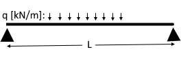
M_max at mid-span, f_max at mid-span
M_max = q · L² / 8 [kN·m]
f_max = 5·q·L⁴ / (384·E·I) [mm]
R_A = R_B = q·L/2 (reactions)
M_max = F · L / 4 [kN·m]
f_max = F·L³ / (48·E·I) [mm]
R_A = R_B = F/2 (reactions)
Cantilever Beam
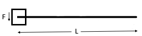
(fixed) (free)
M_max at fixed support, f_max at free end
M_max = F · L [kN·m]
f_max = F·L³ / (3·E·I) [mm]
σ_b = M / W_y = M · e / I [N/mm²]
W_y = I / e [cm³]
e = extreme fibre distance [mm]
f_lim = L / 300 (floors under live load)
f_lim = L / 250 (steel, total deflection)
f_lim = L / 500 (brittle finishes / partitions)
L = span in mm; compare f in mm
Symbol Reference
| q | Distributed load [kN/m] |
| F | Point load [kN] |
| L | Span / length [m] |
| E | Young's modulus [N/mm²] |
| I_y | Second moment of area [cm⁴] |
| e | Extreme fibre distance [mm] |
| M_max | Maximum bending moment [kN·m] |
| f_max | Maximum deflection [mm] |
| σ_b | Bending stress [N/mm²] |
| W_y | Elastic section modulus [cm³] |
Beam Bending – Structural Mechanics Fundamentals
What is a Bending Beam?
A bending beam is the most fundamental structural element in civil engineering. It transfers loads acting perpendicular to its longitudinal axis to the supports through bending moments and shear forces. Every floor slab, downstand beam, steel girder, and timber joist is essentially a bending beam — and must be verified for adequate load-bearing capacity (bending stress ≤ allowable stress) and serviceability (deflection ≤ limit value).
Young's Modulus – Common Materials
| Material | E [N/mm²] | f_y [N/mm²] |
|---|---|---|
| Steel S235 | 210,000 | 235 |
| Steel S355 | 210,000 | 355 |
| Concrete C25/30 | 31,000 | – |
| Concrete C35/45 | 35,000 | – |
| Timber GL28h | 12,600 | 28 |
| Aluminium | 70,000 | ~270 |
Typical Steel Sections I_y [cm⁴]
| Section | I_y [cm⁴] | W_y [cm³] |
|---|---|---|
| IPE 200 | 1,943 | 194 |
| IPE 270 | 5,790 | 429 |
| IPE 360 | 16,270 | 904 |
| HEB 200 | 5,696 | 570 |
| HEB 300 | 25,170 | 1,678 |
Detailed Formula Derivation
1. Bending Moment and Shear Force – Simply Supported Beam, UDL
Shear force: linear from +qL/2 (left) to –qL/2 (right)
Max. bending moment at mid-span: M_max = q · L² / 8
Example: q = 10 kN/m, L = 5 m → M_max = 10 × 25 / 8 = 31.25 kN·m
2. Deflection – UDL (Euler-Bernoulli Beam Theory)
Units: q [N/mm] (1 kN/m = 1 N/mm), L [mm], E [N/mm²], I [mm⁴], f [mm]
Example: q = 10 N/mm, L = 5,000 mm, E = 210,000 N/mm², I = 5,790 cm⁴ = 57.9 × 10⁶ mm⁴
f = 5 × 10 × 5000⁴ / (384 × 210,000 × 57,900,000) = 3.56 mm
Limit L/300 = 5000/300 = 16.7 mm → ✓ satisfied
3. Bending Stress by Navier's Formula
W_y = I_y / e = elastic section modulus [cm³]
Example: M = 31.25 kN·m, I_y = 5,790 cm⁴, e = 135 mm (IPE 270 h/2)
σ = 31.25 × 10⁶ N·mm × 135 mm / (5,790 × 10⁴ mm⁴) = 72.8 N/mm²
Steel S235: σ_allow = 235/1.1 = 214 N/mm² → ✓ sufficient
4. Cantilever – Maximum Bending Moment and Deflection
f_max = F · L³ / (3 · E · I) (at the free end)
Note: A cantilever deflects 16× more than a simply supported beam of equal span under a point load (48/3 = 16×). An increased cross-section or shorter cantilever length is recommended.
Practical Example: Residential Floor Beam
Problem:
Timber floor: beam span L = 4.0 m, spacing 0.625 m. Loads: self-weight 0.75 kN/m² + live load 2.0 kN/m² = 2.75 kN/m². Load per beam: q = 2.75 × 0.625 = 1.72 kN/m. Timber GL28h: E = 12,600 N/mm². Cross-section b/h = 8/22 cm.
Solution:
- I_y = 8 × 22³/12 = 7,099 cm⁴
- M_max = 1.72 × 4.0² / 8 = 3.44 kN·m
- W_y = 7,099 cm⁴ / 11 cm = 645 cm³ → σ = 3,440,000 × 110 / (7,099 × 10⁴) = 5.3 N/mm² < 28 N/mm² ✓
- f = 5 × 1.72 × 4000⁴ / (384 × 12,600 × 70,990,000) = 8.1 mm
- Limit L/300 = 13.3 mm → ✓ satisfied
Frequently Asked Questions
Section modulus: W_y = b·h²/6 [cm³]
Example: b = 20 cm, h = 30 cm → I_y = 20 × 27,000/12 = 45,000 cm⁴, W_y = 20 × 900/6 = 3,000 cm³
Summary
Bending Moment
M = q·L²/8 | M = F·L/4
Cantilever: M = F·L
Deflection
f = 5qL⁴/(384EI)
Limit: L/300 to L/500
Bending Stress
σ = M / W_y
≤ f_y / γ_M (design check)
Typical Applications
- Building construction: Timber floor joists, steel downstand beams, RC slab beams
- Industrial buildings: Crane runways, gantry girders, walkways
- Bridge engineering: Bridge girders, cross-beams, longitudinal beams
- Mechanical engineering: Machine frames, guide rails, test frames
- Cantilevers: Balconies, overhangs, console beams
|
|
|
|