Buckling Load Calculator (Euler)
Critical Load · Buckling Stress · Slenderness Ratio · Buckling Check
Buckling Load Calculator
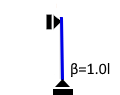
pin–pin
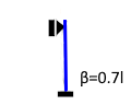
pin–fixed
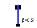
fixed–fixed
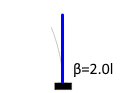
Cantilever
IPE 240: I_z = 284 cm⁴ | IPE 300: I_z = 604 cm⁴
Euler Cases & Formulas
F_crit = π² · E · I / (β · L)² [N]
β = effective length factor | L = system length | L_eff = β·L
| Case | End Conditions | β | Typical Use |
|---|---|---|---|
| Euler 1 | pin – pin | 1.0 | Truss members |
| Euler 2 | pin – fixed | 0.7 | Portal columns |
| Euler 3 | fixed – fixed | 0.5 | Frame columns |
| Euler 4 | fixed – free (cantilever) | 2.0 | Masts, chimneys |
σ_crit = π² · E / λ² [N/mm²]
λ = L_eff / i = β · L / i (slenderness ratio)
i = √(I / A) [mm] radius of gyration
λ ≤ 100 Steel compression members (EC3, typical)
λ ≤ 150 Timber columns (EC5)
λ ≤ 200 Angle sections, secondary members
Euler validity: σ_crit ≤ proportionality limit (approx. 2/3 f_y)
F_Ed ≤ F_crit / γ
γ = 1.5 (EC3 safety format) or γ = 3.0 (classical Euler)
Utilisation ratio η = F_Ed / (F_crit / γ) ≤ 1.0
Symbol Reference
| F_crit | Critical Euler buckling load [N] |
| E | Young's modulus [N/mm²] |
| I_min | Min. second moment of area [cm⁴] |
| β | Effective length factor [–] |
| L | System length (column height) [m] |
| L_eff = β·L | Effective (buckling) length [m] |
| λ | Slenderness ratio [–] |
| i = √(I/A) | Radius of gyration [cm] |
| σ_crit | Euler buckling stress [N/mm²] |
Column Buckling – Stability Theory Fundamentals
What is Column Buckling?
Buckling is a stability failure of slender compression members: once the critical load is exceeded, the column deflects sideways — without the material's compressive strength being reached. Buckling is the most common failure mode for columns, struts, frame rafters and compression chords in trusses. The critical load depends on the bending stiffness EI, the effective length β·L and the end conditions — not on material compressive strength!
Euler Cases Compared (L = 4 m, IPE 240, Steel)
| Case | β | L_eff [m] | F_crit [kN] |
|---|---|---|---|
| Euler 1 | 1.0 | 4.0 | 371 |
| Euler 2 | 0.7 | 2.8 | 757 |
| Euler 3 | 0.5 | 2.0 | 1,484 |
| Euler 4 | 2.0 | 8.0 | 93 |
Radius of Gyration i_z – Typical Sections
| Section | i_z [cm] | A [cm²] |
|---|---|---|
| IPE 240 | 1.97 | 39.1 |
| IPE 270 | 2.21 | 45.9 |
| HEB 200 | 5.07 | 78.1 |
| HEB 300 | 7.58 | 149.1 |
| CHS 100×5 | 3.42 | 15.1 |
Detailed Formula Derivation
1. Euler's Equation – Derived from the Differential Equation of the Deflected Column
E·I·y'' + F·y = 0
Solution (trial function y = A·sin(kx), k² = F/EI) gives k·L = n·π.
For the lowest critical load (n = 1):
F_crit = π² · E · I / L_eff² with L_eff = β · L
Valid only in the elastic range (Euler hyperbola stays below the proportionality limit).
2. Slenderness Ratio and Buckling Stress
σ_crit = F_crit / A = π² · E / λ² [N/mm²]
Euler validity: σ_crit ≤ σ_P (proportionality limit, approx. 0.67 · f_y)
Steel S235: σ_P ≈ 157 N/mm² → λ_min ≈ π·√(E/σ_P) ≈ 115
For λ < 115, Tetmajer/Johnson parabola or EC3 buckling curves (a–d) apply.
3. Effect of Euler Case on Buckling Load
- β = 1.0 (Euler 1): Both ends pinned – corresponds to half a sine wave
- β = 0.7 (Euler 2): One end pinned, one fixed – asymmetric, L_eff = 0.7·L
- β = 0.5 (Euler 3): Both ends fixed – L_eff = 0.5·L, F_crit 4× higher than Case 1
- β = 2.0 (Euler 4): Cantilever (fixed base, free top) – L_eff = 2·L, F_crit 4× lower than Case 1
Practical Example: Portal Frame Column HEB 200, Euler 2
Problem:
Steel column HEB 200, length L = 6.0 m, fixed at base, pinned at top (Euler 2, β = 0.7). Design compressive force F_Ed = 1,200 kN. Check against buckling (γ = 1.5).
Section data HEB 200:
I_z = 2,000 cm⁴, A = 78.1 cm², i_z = 5.07 cm, E = 210,000 N/mm²
Solution:
- L_eff = β · L = 0.7 × 6.0 = 4.2 m
- F_crit = π² × 210,000 × 2,000×10⁴ / (4,200)² = 23,550 kN
- F_Rd = F_crit / γ = 23,550 / 1.5 = 15,700 kN
- F_Ed = 1,200 kN ≤ 15,700 kN → ✓ Check satisfied
- λ = 4,200 / (5.07×10) = 82.8 → Euler range valid
Frequently Asked Questions
- Reduce the effective length – add lateral restraints; changing β from 1.0 to 0.5 multiplies F_crit by 4.
- Increase cross-section height/width – I grows with h³, width only linearly.
- Use hollow sections instead of IPE – RHS/CHS have balanced I in all axes.
- Improve base fixity – a rigid base reduces β from 2.0 to 0.7 (factor 8 on F_crit!).
Summary
Critical Buckling Load
F_crit = π²·E·I / (β·L)²
Unit: N → kN
Slenderness Ratio
λ = β·L / i
i = √(I/A)
Buckling Check
F_Ed ≤ F_crit / γ
η = F_Ed·γ / F_crit ≤ 1
Typical Applications
- Portal frame columns: Steel IPE/HEB, Euler case 2 or 3
- Truss members: Compression chords and verticals, Euler case 1 (pinned)
- Timber columns: Slenderness λ ≤ 150 (EC5)
- Masts and chimneys: Cantilever columns, Euler case 4 (β = 2.0)
- Mechanical engineering: Screw bolts, piston rods, struts
|
|
|
|