Composite Section Calculator
Parallel Axis Theorem · T-Beam · Reinforced Concrete · Steel-Concrete Composite
Composite Section Calculator
 ← y₂ (flange centroid))
y_i = distance of sub-section centroid from reference axis (bottom).
Empty rows are ignored.
Formulas & Theory
ȳ = Σ(A_i · y_i) / Σ(A_i)
y_i = distance of sub-section centroid from reference axis
Sum over all parts i = 1…n
d_i = y_i − ȳ
Distance between the sub-section centroid
and the overall centroid (positive = above centroid)
I_S,i = A_i · d_i²
Contribution due to shift of sub-section axis
to the overall centroidal axis. Always positive!
I_total = Σ(I_i + A_i · d_i²)
I_i = own second moment of area of part i
(Rectangle: I = bh³/12 | Circle: I = πd⁴/64)
W_bot = I_total / ȳ (bottom fibre)
W_top = I_total / (H − ȳ) (top fibre)
H = total height of cross-section
n = E₁ / E₂
Convert material 2 into material 1 equivalent:
A₂,eq = A₂ / n | I₂,eq = I₂ / n
Steel/Concrete: E_s = 210 000 N/mm², E_c ≈ 30 000 N/mm² → n ≈ 7
Own Second Moments – Standard Shapes
| Shape | I [cm⁴] |
|---|---|
| Rectangle b×h | bh³/12 |
| Circle ∅d | πd⁴/64 |
| Hollow circle D/d | π(D⁴−d⁴)/64 |
| Triangle b×h (centroid h/3 from base) | bh³/36 |
Composite Sections – Fundamentals & Applications
What is the Parallel Axis Theorem (Steiner's Theorem)?
The parallel axis theorem is the key tool for calculating the second moment of area of composite cross-sections. It quantifies how the second moment of area of a sub-section increases when its own centroidal axis does not coincide with the overall centroidal axis.
I_total = Σ (I_i + A_i · d_i²)
d_i = distance between the sub-section centroidal axis and the overall centroidal axis
The Steiner term I_S,i = A_i · d_i² is always positive and can exceed the own second moment of area I_i by orders of magnitude when d_i is large. This is why flanges located far from the centroid – as in I-sections and T-beams – deliver exceptional bending stiffness from minimal material.
Typical Composite Sections
- T-beams (steel): welded web + flange plate combinations
- Flanged beams (RC): web + effective compression slab
- Composite beams: steel section + concrete slab (shear studs)
- Timber-concrete: CLT deck + concrete topping
- Sandwich sections: two stiff face sheets + core
Why does a T-beam have a high I?
In a T-beam the flange sits far from the centroid. Its Steiner term A_F · d_F² dwarfs its own I_F. The same principle explains the efficiency of IPE and HEB sections: both flanges are positioned at maximum distance from the centroid, delivering high stiffness with minimum steel weight.
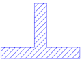
Worked Example: Welded T-Beam
Web 12×300 mm + Flange 200×20 mm
- Sub-sections and positions:
Web: A₁ = 36 cm², y₁ = 15 cm | Flange: A₂ = 40 cm², y₂ = 31 cm - Centroid:
ȳ = (36·15 + 40·31)/(36+40) = 1780/76 = 23.4 cm - Own second moments:
I₁ = 1.2·30³/12 = 2700 cm⁴ | I₂ = 20·2³/12 = 13.3 cm⁴ - Steiner distances:
d₁ = 15−23.4 = −8.4 cm | d₂ = 31−23.4 = +7.6 cm - Steiner terms:
36·8.4² = 2541 cm⁴ | 40·7.6² = 2310 cm⁴ - Total:
I_total = (2700+2541)+(13.3+2310) = 7564 cm⁴ - Section moduli:
W_bot = 7564/23.4 = 323 cm³ | W_top = 7564/8.6 = 880 cm³
Steel-Concrete Composite Beam – Transformed Section
In a composite beam the steel section and concrete slab are connected by shear studs, forcing both to act as one section. Because the materials have different stiffnesses, a transformed section is used: the concrete area is converted to an equivalent steel area by dividing by the modular ratio n = E_s/E_c.
Typical result: IPE 270 + 1200 mm wide slab 120 mm → I_total ≈ 3.9 × I_s
Frequently Asked Questions
State II (cracked): concrete in tension is cracked and ignored. Only the concrete compression zone (depth x) and reinforcement are effective. I_II << I_I. Deflection calculations use an effective mean value (EC2 Method 2: I_eff).
Summary
Centroid
ȳ = Σ(A_i·y_i) / Σ(A_i)
Steiner Term
I_S,i = A_i · d_i²
d_i = y_i − ȳ
Total Second Moment
I_total = Σ(I_i + A_i·d_i²)
Practical Applications
- Welded plate girders: optimise geometry for minimum weight at target stiffness
- RC flanged beams: transformed section (State I) for cracking moment and deflection
- Composite floor beams: profiled sheeting + concrete – full and partial interaction per EC4
- Timber-concrete composites: glulam beam with concrete topping
- Sandwich sections: masts, facade elements, lightweight structures
|
|
|
|