Zener Diode Series Resistor for Variable Load
Calculate series resistor for a Zener diode with fluctuating load current
Variable Load Calculator
Variable Load
For fluctuating load currents. The Zener diode must be able to handle the entire fluctuation range and must be dimensioned accordingly.
Typical Load Scenarios
Variable Load Zener Regulator
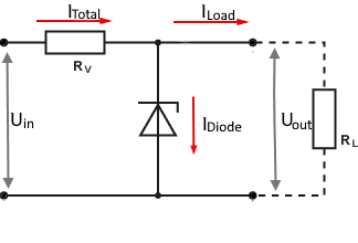
Circuit diagram: Zener diode with variable load current
Critical Differences
- Zener diode must handle entire current fluctuation range
- Maximum Zener power = UZ × (Imax - Imin + IZ,min)
- At Imin = 0, total current flows through Zener diode
- High power dissipation with large current fluctuations
Current Distribution
Standard Zener Diodes
Practical Calculation Examples for Variable Loads
Example 1: Digital Circuit (0-100mA)
Given: Uin = 12V, UZ = 5.1V, IL = 0-100mA
Step-by-Step Calculation
Problem: High Zener power at zero load!
Example 2: LED Dimmer (10-50mA)
Given: Uin = 15V, UZ = 12V, IL = 10-50mA
Improved Design
Advantage: Minimum load reduces Zener stress
Example 3: Critical Scenario - Sensor with On/Off (0-200mA)
Given: Uin = 24V, UZ = 15V, IL = 0-200mA (Sensor with heater)
Problem Analysis and Solution
Recommendation: Use LDO regulator or switching regulator for better efficiency.
When to use variable load Zener regulators?
Better Alternatives
Theory of Zener Diode Voltage Regulation with Variable Load
Operating Principle with Variable Load
With variable load, the Zener diode must compensate for the entire current fluctuations. The total current through the series resistor remains constant, but the current distribution between load and Zener diode changes significantly.
Critical Operating Points
- At maximum load: IZ = IZ,min (Minimum current through Zener diode)
- At minimum load: IZ = Itotal - IL,min (Maximum current through Zener diode)
- Critical case: IL,min = 0 → entire current through Zener diode
- Dimensioning: Design Zener diode for maximum current
Mathematical Relationships
Total Current:
Series Resistor:
Maximum Zener Current:
Maximum Zener Power:
Critical Disadvantages
- Very high Zener power with large current fluctuations
- Poor efficiency with on/off loads
- Expensive, high-power Zener diodes required
- High heat generation
- Limited regulation accuracy
Design Rules
- Dimension Zener diode for maximum current
- Choose at least 2× calculated power
- Provide adequate cooling
- If Imin = 0: check alternatives
- Weigh efficiency vs. simplicity
Applications
- Suitable: Sensor with low current fluctuation
- Suitable: Dimmer with high baseline load
- Unsuitable: On/off consumers
- Unsuitable: High currents with large fluctuation
Efficiency Considerations
| Load Ratio Imin:Imax | Relative Zener Load | Recommendation | Alternative |
|---|---|---|---|
| 0:1 (On/Off) | Very high (100%) | Avoid | Switching regulator, LDO |
| 1:4 | High (75%) | Critical review | LDO regulator |
| 1:2 | Medium (50%) | Acceptable | LDO for high currents |
| 2:3 | Low (33%) | Suitable | - |
Comparison of Regulation Types
Zener Diode Regulator
LDO Regulator
Switching Regulator
Symbol Directory
| IL,max | Maximum load current [A] |
| IL,min | Minimum load current [A] |
| IZ,min | Minimum Zener current for stability [A] |
| IZ,max | Maximum Zener current (at IL,min) [A] |
| Itotal | Constant total current through Rv [A] |
| PZ,max | Maximum power dissipation of Zener diode [W] |
| ΔIL | Current fluctuation range (Imax - Imin) [A] |
|
|