Calculate Voltage Divider
Calculator and formula for calculating an unloaded voltage divider
Unloaded Voltage Divider
Input Options
For calculation, you need at least three known values:
• 2 voltage values + 1 resistance value
• 1 voltage value + 2 resistance values
Voltage Divider Principle

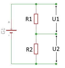
Circuit diagram: Unloaded voltage divider
Basic Principle
The voltage divider is a series circuit of two resistors:
- Same current through both resistors
- Voltage division proportional to the resistances
- Utotal = U₁ + U₂
- Rtotal = R₁ + R₂
Voltage Divider Formula
Typical Applications
- Generate reference voltages
- ADC voltage adaptation
- Sensor interface circuits
- Bias adjustment for amplifiers
|
|
Voltage Divider Formulas and Theory
1. Voltage divider formula
For the output voltage U₂:
Proportional to resistance R₂
2. Calculation via current
Alternative calculation method:
3. Resistance calculation
From known voltages:
When R₁ and voltages are known
Practical Calculation Examples
Example 1: Calculate voltage U₂
Given: Utotal = 12V, R₁ = 3kΩ, R₂ = 6kΩ
Find: Voltage U₂
✓ Check: U₁ = 4V, U₁ + U₂ = 12V ✓
Example 2: Calculate resistance R₂
Given: Utotal = 9V, U₂ = 3V, R₁ = 1kΩ
Find: Resistance R₂
✓ Ratio: 3V/6V = 500Ω/1000Ω = 1:2
Example 3: Generate reference voltage
Task: A reference voltage of 2V should be generated from 5V. R₁ = 1kΩ is given.
Find: Resistance R₂
Check: With 680Ω: U₂ = 5V × (680Ω / 1680Ω) = 2.02V
Practical Applications and Design Guidelines
Common Applications
- Reference voltages: Generation of stable reference voltages for analog circuits
- ADC interfacing: Voltage adaptation for analog-to-digital converters
- Sensor interfaces: Signal conditioning of sensor signals
- Bias circuits: Operating point adjustment in amplifiers
- Level converters: Adaptation between different logic levels
- Measurement circuits: Voltage reduction for measuring instruments
Design Recommendations
- Total resistance: 1kΩ - 100kΩ for typical applications
- Load resistance: Should be at least 10x larger than R₂
- Tolerances: Precision resistors (±1% or better) for accurate division
- Temperature coefficient: Same TC values for both resistors
Comparison of Circuit Types
| Circuit Type | Characteristic | Application |
|---|---|---|
| Unloaded voltage divider | Constant division ratio | Reference voltages, measurement circuits |
| Loaded voltage divider | Division ratio changes with load | Signal sources with variable load |
| Voltage regulator | Constant output voltage | Power supplies |
Important Notes
- Consider loading: Division ratio changes under load
- Current consumption: Voltage dividers consume continuous current
- Temperature drift: Resistance changes affect output voltage
- Noise: Higher resistances generate more thermal noise
- Frequency response: Parasitic capacitances can cause interference at high frequencies
Related Calculators
For applications with changing loads:
Loaded Voltage DividerPractical Tips
- Use metal film resistors for precision
- Calculate power dissipation: P = U²/R
- Buffer high-impedance outputs with operational amplifiers
- Use bypass capacitors for RF applications