Function Rectify1
Calculates voltages and currents behind a half-wave rectifier
Description
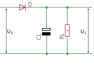
The \(Rectify1\) function calculates different voltages and the current behind a Half-wave rectifier with charging capacitor and load resistor.
The voltages in idle and under load, the ripple voltage and the current through the load resistor are calculated.
The drop-out voltage at the diode is taken into account. A value of 0.7 volts is usual for silicon rectifiers.
For the internal resistance of the power source, the resistance of the secondary winding of the transformer is essential. In the heavy current range, the resistance of the connection lines can also play a role. Transformerless circuits usually have a series resistor to limit the inrush current whose value (e.g. 5.6 Ohm) is used as the internal resistance.
As a result, the function returns an object in which the calculated values are contained.
Syntax
Rectify1 (U1, Ri, RL, CL, f, UD) = Record
Symbols of arguments
U1
RMS value of the alternating voltage in volts before the rectifier
Ri
Internal resistance of the power source in ohms
RL
Load resistance in ohms
CL
Charge consensator in Farads
f
Frequency of the input voltage in Hz
UD
Voltage drop of the rectifier diode
Example
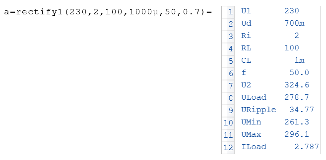
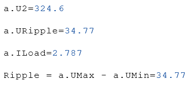
If the result is assigned to a variable, the individual values can be accessed via the variable. See the following example.
Results symbols
U2
Open-circuit DC voltage behind the rectifier
ULoad
Average DC voltage behind the rectifier under load
URipple
Superimposed ripple voltage behind the rectifier in Vss
UMax
Maximum peak voltage after the rectifier
UMin
Minimum voltage behind the rectifier
ILoad
Current through the load resistance in A.
|
|