Calculate RLC Series Circuit
Calculator and formulas for calculating voltage and power of an RLC series circuit
Calculate RLC Series Circuit
RLC Series Circuit
The calculator computes voltages, powers, current, impedance and reactance in the series circuit of a resistor, an inductor and a capacitor.
RLC Series Circuit
Series Circuit Properties
- Same current through all components
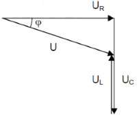
- Geometric addition of component voltages
- UL and UC are 180° out of phase
- Phase shift between 0° and ±90°
Basic Formulas
Voltage and impedance triangle according to Pythagoras
Phase Relationships
- R: Current and voltage in phase
- L: Voltage leads by +90°
- C: Voltage lags by -90°
- Resulting phase: Depends on XL - XC
RLC Series Circuit - Theory and Formulas
Fundamentals of RLC Series Circuit
The total resistance of the RLC series circuit in the AC circuit is called impedance Z. Ohm's law applies to the complete circuit. The current is the same at every measurement point.
Voltage Triangle
Voltages
Impedance Triangle
Reactances and Current
Reactances
Frequency-dependent resistances of inductor and capacitor.
Current
Current is the same in all components (series circuit).
Component Voltages
Voltages across individual components.
Power Triangle
Powers
Frequency Behavior
Low Frequencies
- XC >> XL
- Capacitive behavior
- Negative phase shift
- High impedance
Resonance Frequency
- XL = XC
- Z = R (minimum)
- φ = 0°
- Maximum current
High Frequencies
- XL >> XC
- Inductive behavior
- Positive phase shift
- High impedance
Practical Applications
Filter circuits:
Resonant circuits:
Power electronics:
Design Guidelines
Important Design Aspects
- Resonance: At f₀ = 1/(2π√LC), Z is minimum
- Voltage enhancement: UL and UC can exceed U
- Quality factor: Q = (XL or XC)/R at resonance
- Losses: Consider ESR of components
- Temperature effects: L and C are temperature dependent
- Tolerances: Significantly affect resonance frequency