Resistors in Series
Understand series circuits and how to calculate total resistance, current, and voltage distribution
Overview
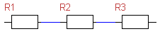
In a series connection, multiple resistors are connected in a line, so the current flows through each resistor in sequence. The same current flows through all resistors in a series circuit.
The same current flows through all resistors, but the voltage divides across them proportionally to their resistance values. This is opposite to parallel circuits.
Total Resistance
In a series circuit, the total resistance is simply the sum of all individual resistances.
Resistances add directly in series. Adding more resistors always increases the total resistance.
Key observation
The total resistance in a series circuit is always greater than any individual resistance. Each resistor adds to the total resistance.
Current in Series Circuit
The same current flows through all resistors in a series circuit. Using Ohm's Law, we can calculate this current from the total voltage and total resistance.
The total current through all resistors is identical:
Using Ohm's Law with total values:
Voltage Division in Series
In a series circuit, the total voltage divides across the individual resistors. The voltage distribution is proportional to the resistance values.
Voltage Sum Rule
The total voltage is the sum of the individual voltages:
Voltage Divider Principle
The voltage across each resistor is proportional to its resistance. The ratio of voltages equals the ratio of resistances:
Individual Voltage Formulas
The voltage across a specific resistor can be calculated in two ways:
Method 1: Using Current
Method 2: Using Ratio
Worked Example
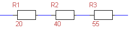
Calculate Series Resistor Circuit
Given:
- \(R_1 = 20\,\Omega\)
- \(R_2 = 40\,\Omega\)
- \(R_3 = 55\,\Omega\)
- \(U_{\text{total}} = 230\,\text{V}\)
Step 1: Calculate total resistance
Step 2: Calculate total current
Step 3: Calculate individual voltages
Voltage across \(R_1\):
Method 2: \(\displaystyle U_1 = \frac{R_1 \cdot U_{\text{total}}}{R_{\text{total}}} = \frac{20 \cdot 230}{115} = 40\,\text{V}\)
Voltage across \(R_2\):
Method 2: \(\displaystyle U_2 = \frac{R_2 \cdot U_{\text{total}}}{R_{\text{total}}} = \frac{40 \cdot 230}{115} = 80\,\text{V}\)
Voltage across \(R_3\):
Method 2: \(\displaystyle U_3 = \frac{R_3 \cdot U_{\text{total}}}{R_{\text{total}}} = \frac{55 \cdot 230}{115} = 110\,\text{V}\)
Verification:
Summary: Series vs Parallel
Series Circuit
Resistance: \(R = R_1 + R_2 + \ldots\)Current: Same everywhere
Voltage: Divides proportionally
Parallel Circuit
Resistance: \(\frac{1}{R} = \frac{1}{R_1} + \frac{1}{R_2} + \ldots\)Current: Divides proportionally
Voltage: Same everywhere
Key Properties of Series Circuits
- Same current flows through all resistors
- Total resistance is sum of individual resistances
- Total voltage is sum of individual voltages
- Voltage divides proportionally to resistance values
- Higher resistance resistor gets higher voltage drop
- Total resistance is always greater than any individual resistor
- If one component fails (opens), the entire circuit breaks
|
|
|
|