Calculate RC Integrator
Calculator and formulas for calculating an RC integrator
Calculate Integrator
RC Integrator
This function allows you to calculate the properties of an RC integrator. The function calculates the capacitor, resistor, or the period/frequency.
Integrator
Pulse Shaper Stage
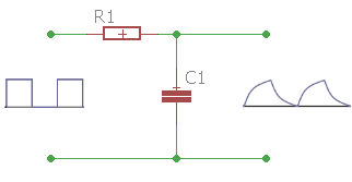
The integrator works as a pulse shaper stage. The RC circuit generates a ramp-shaped output from a square wave input.


Time Constant τ (tau)
The time constant of an RC circuit is the product of R · C. The unit is seconds. The symbol is the Greek letter τ (tau).
After 5τ, the charge is about 99.3%.
|
|
|
|
RC Integrator - Theory and Formulas
How the Integrator Works
The integrator works as a pulse shaper stage. The RC circuit generates a ramp-shaped voltage at the output from a square wave input. Integration occurs through the slow charging of the capacitor.
Pulse Shapes for Different Time Constants
t1 = 5τ Optimal Integration

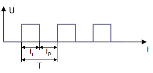
If the length of the square pulse (t1) is five times the time constant τ, an optimal ramp shape is produced.
t1 > 5τ Steeper Ramps
If the pulse duration of the input voltage is greater than 5τ, steeper ramp shapes are produced.
Time Constant and Charging Behavior
The Time Constant τ (tau)
- The time constant is the product of R × C
- Unit: seconds (s)
- Symbol: τ (Greek letter tau)
- After 5τ, the charge is about 99.3%
- Determines the speed of ramp formation
- For good integration: t1 ≥ 5τ
Practical Applications
Signal Processing:
Measurement Technology:
Control Engineering:
Design Guidelines
Optimal Dimensioning
- For good integration: t1 ≥ 5τ
- For linear ramps: t1 ≥ 10τ
- Output amplitude: Depends on the time constant
- Ramp slope: Proportional to 1/τ
- Loading: High input resistance of the following stage
- Frequency range: Depends on τ and desired accuracy
Mathematical Relationships
Basic Formulas
Where n is the factor (typically 5 or greater)
Conversions
Calculation of components for a given t1
Integrator vs. Differentiator
Differences
Integrator (RC):
- Output at the capacitor
- Generates ramps from square waves
- Slow changes
- Low-pass characteristic
Differentiator (CR):
- Output at the resistor
- Generates spikes from square waves
- Fast changes
- High-pass characteristic
|
|