Calculate RC Parallel Circuit
Calculator and formulas for calculation of current and power of an RC parallel circuit
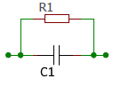
RC Parallel Circuit
RC Parallel Circuit
The calculator computes current, power, apparent and reactive resistance in the parallel connection of a resistor and a capacitor.
Circuit Diagram
Parallel Circuit Properties
- Same voltage across all components
- Total current is the sum of the branch currents
- Total impedance is less than the smallest individual resistance
- Phase shift between branch currents
Basic Formulas
Total current and impedance of the RC parallel circuit.
Powers
- Active Power P: Only in the resistor
- Reactive Power Q: Only in the capacitor
- Apparent Power S: Geometric sum
RC Parallel Circuit - Theory and Formulas
Basics of the RC Parallel Circuit
The total resistance of the RC parallel circuit in AC is called apparent resistance or impedance Z. Ohm's law applies to the entire circuit. In the ohmic resistor, current and voltage are in phase. In the capacitive reactance of the capacitor, the voltage lags the current by −90°.
Formulas and Calculations
Current Triangle
| I | Total current |
| IR | Current through resistor |
| IC | Current through capacitor |
Admittance Triangle
| G | Conductance [1/R] |
| BC | Susceptance [1/XC] |
| Y | Admittance [1/Z] |
Impedance Triangle
| XC | Capacitive reactance |
| R | Resistance |
| Z | Impedance |
Power Calculation
Active Power
The active power is only dissipated in the resistor and converted to heat.
Reactive Power
The reactive power oscillates between the capacitor and the generator.
Apparent Power
The apparent power is a purely mathematical quantity.
Special Features of the Parallel Circuit
Important Properties
- The total current is the geometric sum of the branch currents
- The voltage is the same across all components
- The total resistance is less than the smallest individual resistance
- The branch currents form a right triangle
- Admittances are used in parallel circuits
- The phase shift between current and voltage depends on frequency
Practical Applications
Power Factor Correction:
Filter Applications:
Oscillators:
|
|