Calculate RC Low Pass Filter
Calculator and formulas for calculating the parameters of an RC low pass filter
Calculate RC Low Pass
RC Low Pass Filter
This function calculates the properties of a low pass filter from resistor and capacitor values. For the given frequency, the output voltage, attenuation, and phase shift are calculated.
RC Low Pass Circuit
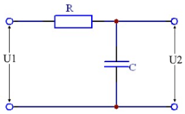
Symbol Explanations
Low Pass Characteristics
- Passes low frequencies
- Attenuates high frequencies
- -3dB at cutoff frequency
- -20dB/decade roll-off
- Phase shift 0° to -90°
Cutoff Frequency
At the cutoff frequency, the attenuation is -3dB.
RC Low Pass - Theory and Formulas
RC Low Pass Basics
An RC low pass is a first-order filter that passes low frequencies and attenuates high frequencies. The output is taken across the capacitor. At high frequencies, the capacitor has a low resistance, at low frequencies, a high resistance.
Important Formulas
Voltage Ratio
or simpler with XC:
Reactance
The capacitive reactance decreases with increasing frequency.
Attenuation and Phase
Attenuation in dB
or directly:
Phase Shift
or:
Cutoff Frequency and Characteristic Values
Cutoff Frequency
At fg: Attenuation = -3dB, Phase = -45°
Impedance
Total impedance of the circuit
Time Constant
Characteristic time of the circuit
Frequency Response
Frequency Response Characteristics
- Low frequencies (f ≪ fg): No attenuation, phase → 0°
- Cutoff frequency (f = fg): -3dB attenuation, phase = -45°
- High frequencies (f ≫ fg): Strong attenuation, phase → -90°
- Slope: -20dB/decade above fg
- Transfer function: H(jω) = 1/(1 + jωRC)
Practical Applications
Audio Filters:
Smoothing Filters:
Timing Elements:
Design Guidelines
Important Design Aspects
- Cutoff frequency selection: Should be well above the highest frequency to be transmitted
- Capacitance selection: Larger C → lower fg, but larger components
- Resistance selection: Compromise between input impedance and signal level
- Loading effects: Following stage should have high input impedance
- Tolerances: Component variations affect the cutoff frequency
Mathematical Relationships
Basic Formulas
Relationship between time constant and cutoff frequency
Conversions
Calculation of components for a given cutoff frequency
Low Pass vs. High Pass
Differences
Low Pass (RC):
- Output at the capacitor
- Attenuates high frequencies
- Phase: 0° to -90°
- Smoothing characteristic
High Pass (CR):
- Output at the resistor
- Attenuates low frequencies
- Phase: +90° to 0°
- Differentiating characteristic
|
|