Calculate RC Series Circuit
Calculator and formulas for calculating the voltage and power of an RC series circuit
RC Series Circuit Calculator
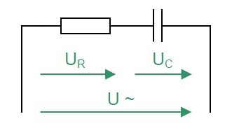
RC Series Circuit
This function calculates the voltages, powers, current, apparent and reactive resistance of a series connection of a resistor and a capacitor.
RC Series Circuit
Series Circuit Properties
- Same current through all components
- Total voltage is the sum of the partial voltages
- Impedance greater than the largest individual resistance
- Phase shift between voltages
Basic Formulas
Voltage and resistance triangle according to Pythagoras
Power Triangle
- P: Active power (in the resistor)
- Q: Reactive power (in the capacitor)
- S: Apparent power (total power)
RC Series Circuit - Theory and Formulas
Basics of the RC Series Circuit
The total resistance of the RC series circuit in AC is called apparent resistance or impedance Z. Ohm's law applies to the entire circuit. The current is the same at every measuring point. In the ohmic resistor, current and voltage are in phase. In the capacitive reactance of the capacitor, the voltage lags the current by −90°.
Voltage Triangle
Voltages
Impedance Triangle
Powers in the RC Series Circuit
The multiplication of the instantaneous values of voltage U and current I gives the power curve.
Active Power
The active power is converted to heat in the resistor.
Reactive Power
The reactive power oscillates between the capacitor and the generator.
Apparent Power
The apparent power is a purely mathematical quantity.
Power Triangle
Power Relationships
Power factor cos(φ)
Power Factor cos(φ)
Power Factor
The power factor indicates how much of the apparent power S is converted as active power P. The closer cos(φ) is to 1, the more efficient the energy transfer.
Practical Applications
Filter Circuits:
Timing Circuits:
Coupling:
Phase Behavior
Phase Shift
- Resistor: Current and voltage in phase (φ = 0°)
- Capacitor: Voltage lags current by -90°
- Total circuit: Phase angle between 0° and -90°
- Capacitive: For XC > R, the circuit is capacitive
- Resistive: For R > XC, the ohmic character dominates
Frequency Dependence
Low Frequencies
- XC is large
- Impedance is dominated by XC
- Large phase shift
- Capacitor acts as a block
High Frequencies
- XC is small
- Impedance is dominated by R
- Small phase shift
- Capacitor acts as a short circuit
Design Guidelines
Important Design Aspects
- Voltage distribution: Depends on frequency and component values
- Resonance: At f = fg, Z is minimal
- Voltage withstand: Partial voltages can be greater than total voltage
- Loss factor: Real capacitors have additional ESR
- Tolerances: Component variations affect behavior
- Temperature effect: Capacitance and resistance are temperature dependent
|
|