Voltages at Full-Wave Rectifier
Calculator for calculating RMS and average voltage at bridge rectifier
Full-Wave Rectifier Calculator
Bridge Rectification
Calculation without filter capacitor. Both half-waves are utilized, resulting in lower ripple and better transformer utilization.
Rectifier Types
Voltage Diagram
Voltage Comparison
Comparison of different voltage values at the full-wave rectifier. The average voltage is the DC component.
Operating Principle
- Both half-waves are rectified
- Better transformer utilization than half-wave rectifier
- Lower ripple in output voltage
- Higher output power possible
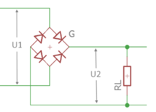
Circuit diagram: Bridge rectifier (4 diodes)
Practical Calculation Examples
Example 1: Mains Transformer 230V
Given: Mains voltage 230V (RMS value), Bridge rectifier
Step-by-Step Calculation
Application: Basis for DC power supplies after filtering
Example 2: 24V Transformer
Given: 24V secondary voltage (RMS value), Bridge rectifier
Low-Voltage Rectification
Note: At low voltages, diode loss becomes significant
Example 3: Comparison Bridge vs. Center-Tap Rectifier
Given: 15V secondary voltage, comparison of both rectifier types
Detailed Comparison
Bridge Rectifier (4 diodes)
Center-Tap Rectifier (2 diodes)
But: Bridge rectifier doesn't require center tap on transformer
Efficiency Considerations
Practical Applications
Theory of Full-Wave Rectifier
Operating Principle
The full-wave rectifier uses both half-waves of the AC voltage for rectification. This leads to better transformer utilization and lower ripple in the output voltage compared to the half-wave rectifier.
Bridge Rectifier vs. Center-Tap Rectifier
| Property | Bridge Rectifier | Center-Tap Rectifier |
|---|---|---|
| Number of Diodes | 4 | 2 |
| Voltage Drop | 2 × UD = 1.4V | 1 × UD = 0.7V |
| Transformer | Simple secondary winding | Center tap required |
| Efficiency | Lower (higher losses) | Higher (lower losses) |
| Application | Standard for DC power supplies | High-frequency power supplies |
Mathematical Relationships
Peak value after diodes:
Average value (DC component):
RMS value output:
Form factor:
Ripple and Spectrum
- Fundamental ripple frequency: 2 × mains frequency (100Hz at 50Hz mains)
- Ripple: Significantly lower than half-wave rectifier
- Spectrum: Harmonics at 100Hz, 200Hz, 300Hz, ...
- Filter effort: Lower effort required for smoothing
Advantages
- Better transformer utilization
- Lower ripple
- Higher output power possible
- Lower ripple frequency (100Hz)
- Proven, robust technology
Disadvantages
- Higher diode losses (4 vs 2 diodes)
- More components required
- Higher reverse voltage per diode
- More complex circuit
Application Areas
- DC Power Supplies: Linear and switching
- Battery Chargers: Simple design
- Motor Drives: DC motor supply
- Measuring Instruments: Analog instruments
- Audio: Amplifier power supplies
Voltage Waveforms
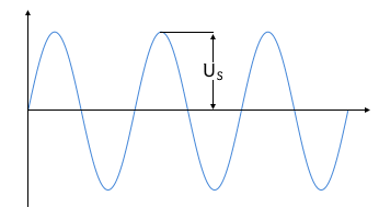
Half-wave rectifier: Only positive half-waves
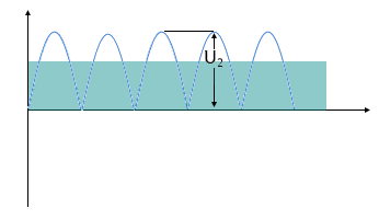
Full-wave rectifier: Both half-waves utilized
Symbol Directory
| U1,RMS | Input voltage (RMS value) [V] |
| U1s | Input voltage (peak value) [V] |
| U2s | Output voltage (peak value after diodes) [V] |
| Uavg | Average value of output voltage (DC component) [V] |
| URMS,out | RMS value of output voltage [V] |
| UD | Diode forward voltage [V] |
| F | Form factor (URMS/Uavg) [-] |
|
|