Full-Wave Rectifier with Filter Capacitor
Calculate ripple voltage and charging voltage at bridge rectifier
Bridge Rectifier with Smoothing
With Filter Capacitor (Smoothing Capacitor)
Calculation of ripple voltage and voltage drop under load. The filter capacitor smooths the pulsating DC voltage.
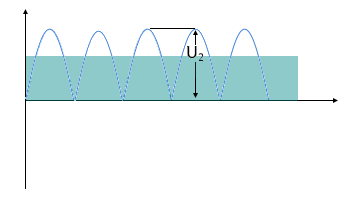
Voltage Diagram with Ripple Voltage
Voltage Analysis
The right column shows the minimum output voltage (blue) and the ripple voltage (red stacked). The total height corresponds to the maximum voltage.
Filter Capacitor Principle
- Capacitor charges to peak voltage
- Discharge through load resistance between pulses
- Ripple voltage due to charge/discharge cycles
- Larger capacitor = lower ripple voltage
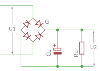
Circuit diagram: Bridge rectifier with filter capacitor
Typical Values
Capacitor Dimensioning
Practical Limits
Theory of Rectification with Filter Capacitor
Operating Principle
The filter capacitor (smoothing capacitor) smooths the pulsating DC voltage of the rectifier. It charges to the maximum voltage during peak times and discharges through the load resistance until the next charging pulse arrives.
Charging and Discharging Process
- Charging time: Very short (only around the peak value of the sine voltage)
- Discharging time: Between charging pulses (at 50Hz mains: ~10ms)
- Charging current: Very high, as only short charging time available
- Discharging current: Constant, determined by load resistance
Mathematical Relationships
No-load voltage:
Ripple voltage:
Load voltage:
Reverse voltage:
Design Criteria
| Parameter | Uncritical | Acceptable | Critical |
|---|---|---|---|
| Ripple Factor | < 5% | 5-15% | > 15% |
| Capacitor per Ampere | > 5000µF/A | 2000-5000µF/A | < 2000µF/A |
| Internal Resistance | < RL/20 | RL/20 to RL/10 | > RL/10 |
| Transformer Utilization | 90-95% | 80-90% | < 80% |
Advantages
- Simple construction
- Low cost
- High reliability
- No switching frequency interference
- Good overload capability
Disadvantages
- High ripple voltage
- Poor load regulation
- Large, heavy capacitors
- High peak current through diodes
- Transformer over-dimensioning needed
Applications
- Simple Power Supplies: For non-critical applications
- Pre-stabilization: For linear regulators
- Battery Chargers: With downstream regulation
- Motor Drives: DC motor supply
- Audio: With additional filtering
Voltage Waveforms and Component Selection
Without capacitor: Pulsating DC voltage
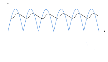
With capacitor: Smoothed voltage with ripple component
Capacitor Selection
Diode Selection
Symbol Directory
| UNo-load | No-load voltage (without load) [V] |
| ULoad | Output voltage under load [V] |
| URipple | Ripple voltage (peak-to-peak) [V] |
| UReverse | Maximum diode reverse voltage [V] |
| CL | Filter capacitor (smoothing capacitor) [µF] |
| Ri | Internal resistance of source [Ω] |
| RL | Load resistance [Ω] |
| f | Mains frequency [Hz] |
|
|