Half-Wave Rectifier with Filter Capacitor
Calculate ripple voltage and charging voltage of half-wave rectifier
Half-Wave Rectification with Capacitor
Capacitor Smoothing
The filter capacitor reduces ripple voltage and stabilizes the output voltage. Internal resistance, diode forward voltage and frequency are considered.
Voltage Diagram
Voltage Comparison with Ripple Voltage
The right blue bar shows the minimum output voltage. The red area corresponds to the ripple voltage (VPP). The total height corresponds to the maximum output voltage.
Circuit Type
Half-wave rectifier with filter capacitor
- Capacitor charges during positive half-wave
- Discharge through load resistance during blocking phase
- Significantly reduced ripple voltage
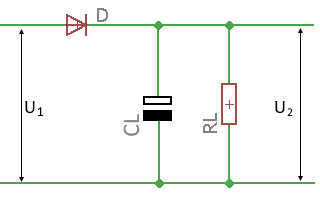
Circuit diagram: Half-wave rectifier with filter capacitor
Practical Calculation Example
Example: 12V Power Supply with Half-Wave Rectifier
Given: Transformer secondary voltage URMS = 15V, Filter capacitor C = 1000µF, Load resistance RL = 100Ω, Internal resistance Ri = 2Ω, Frequency f = 50Hz
Step 1: Calculate no-load voltage
Step 2: Output voltage under load
Step 3: Calculate ripple voltage
Step 4: Min/Max voltages
Step 5: Load current and reverse voltage
Capacitor Dimensioning
Practical Notes
Theory of Half-Wave Rectifier with Capacitor
Operating Principle
The half-wave rectifier with filter capacitor significantly improves the smoothing of the output voltage. During the positive half-wave, the diode conducts and the capacitor charges to the peak voltage. During the negative half-wave, the capacitor discharges through the load resistance.
Detailed Operation
- Charging phase: Diode conducts, capacitor charges quickly
- Discharging phase: Diode blocks, capacitor discharges slowly through RL
- Smoothing: Capacitor bridges the blocking time of the diode
- Ripple voltage: Remains due to incomplete smoothing
Mathematical Relationships
No-load voltage:
Output voltage under load:
Ripple voltage:
Reverse voltage:
Component Influence
- Capacitor C: Larger capacitor → lower ripple voltage
- Load resistance RL: Higher resistance → lower ripple voltage
- Internal resistance Ri: Higher resistance → lower output voltage
- Frequency f: Higher frequency → lower ripple voltage
Disadvantages
- High inrush current
- Poor transformer utilization
- Voltage dependency on load
- Remaining ripple voltage
- High diode reverse voltage required
Advantages
- Significantly reduced ripple voltage
- Higher output voltage
- Simple construction
- Cost-effective solution
- Proven technology
Typical Applications
- Simple DC power supplies
- Battery chargers
- Amplifier power supply
- LED lighting
- DC motors
Voltage Waveform Under Load
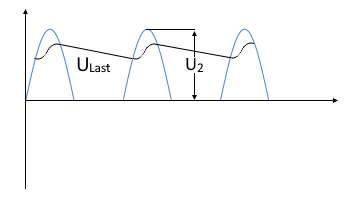
Voltage waveform shows charging during positive half-wave and discharge through load resistance
Symbol Directory
| URMS | RMS value of input voltage [V] |
| UNo-load | No-load voltage without load resistance [V] |
| ULoad | Output voltage at load resistance [V] |
| URipplePP | Ripple voltage (peak-to-peak) [V] |
| UD | Diode forward voltage (typ. 0.7V) [V] |
| Ri | Internal resistance of current source [Ω] |
| RL | Load resistance [Ω] |
| CL | Filter capacitor [F] |
| f | Mains frequency [Hz] |
| UReverse | Maximum reverse voltage at diode [V] |
|
|