Voltages in Half-Wave Rectifier
Calculate RMS voltage and average voltage of half-wave rectification
Calculate Half-Wave Rectification
Input Voltage
Enter either the RMS voltage or the peak voltage of the AC voltage. The diode forward voltage is automatically considered.
Voltage Diagram
Voltage Comparison
Circuit Type
Half-Wave Rectifier
- Only positive half-waves pass through the diode
- Simplest form of rectification
- High ripple in output voltage
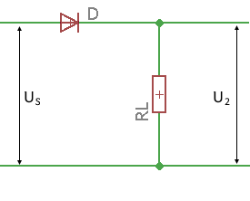
Circuit diagram: Half-wave rectifier
Theory of Half-Wave Rectifier
Operating Principle
The half-wave rectifier is the simplest type of rectification. The load resistor takes over the role of the series resistor here. Only the positive half-waves of the input voltage reach the load resistor, the negative ones are "cut off" by the diode. Such a voltage is also called pulsating DC voltage.
Characteristic Properties
- High Ripple: Only every second half-wave is transmitted
- Poor Transformer Utilization: Only 50% of available energy is used
- Simple Construction: Can also be operated without a transformer
- Low Cost: Only one diode required
Voltage Relationships
Output voltage after diode:
Peak voltage minus diode forward voltage
DC component (average value):
About 31.8% of peak voltage
RMS value:
50% of peak voltage
Form factor:
Ratio of RMS to average value
Disadvantages
- High ripple (100% with pure load)
- Poor transformer utilization
- High harmonic content
- Low output voltage
Advantages
- Simplest construction
- Low cost
- Few components
- Can be operated without transformer
Typical Applications
- Simple power supplies
- Battery chargers
- DC motors with low requirements
- Measuring instruments
Input Voltage (AC Voltage)
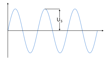
Sinusoidal AC voltage at input
Output Voltage (rectified)
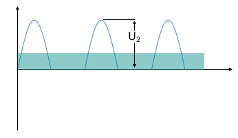
Pulsating DC voltage at output
Symbol Directory
| UG | DC component (average value) [V] |
| URMS | RMS value of output voltage [V] |
| US | Input peak voltage [V] |
| U₂ | Output peak voltage after diode [V] |
| UD | Diode forward voltage (typ. 0.7V) [V] |
| π | Pi ≈ 3.14159 |
|
|