Calculate RL Series Circuit
Calculator and formulas for calculating an RL series circuit
RL Series Circuit Calculator
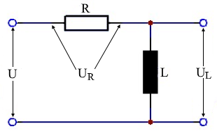
RL Series Circuit
The calculator calculates voltages, powers, current, apparent and reactive resistance for a series circuit consisting of a resistor and an inductor. Enter the values for inductor, resistor, frequency and voltage.
Circuit Diagram & Parameters
Parameter Legend
| U | Applied voltage |
| UR | Voltage across resistor |
| UL | Voltage across inductor |
| I | Current |
| R | Ohmic resistance |
| XL | Inductive reactance |
| Z | Impedance - total resistance |
| P | Real power |
| Q | Inductive reactive power |
| S | Apparent power |
| φ | Phase shift in ° |
Example Calculations
Practical Calculation Examples
Example 1: Low Frequency Motor
Given: L = 50 mH, R = 10 Ω, f = 50 Hz, U = 230 V
Example 2: Audio Crossover
Given: L = 1 mH, R = 4 Ω, f = 3 kHz, U = 12 V
Example 3: RF Circuit
Given: L = 10 µH, R = 50 Ω, f = 10 MHz, U = 5 V
Important Conversions
Inductance units:
Voltage units:
RL Series Circuit - Theory and Formulas
What is an RL Series Circuit?
In an RL series circuit, an ohmic resistor R and an inductance L are connected in series. The same current flows through both components, but the voltage is distributed according to the respective resistance values. The total voltage is the geometric sum of the partial voltages.
Calculation Formulas
Voltage Triangle
Total Voltage
Geometric addition of partial voltages
Active Voltage
Voltage across ohmic resistor
Reactive Voltage
Voltage across inductance
Current
Current is the same everywhere
Impedance Triangle
Total Impedance
Total resistance of the circuit
Resistance
Ohmic resistance
Reactance
Frequency-dependent reactance
Phase Angle
Phase shift between U and I
Power Triangle
Apparent Power
Total power of the circuit
Real Power
Usable power (only in resistor)
Reactive Power
Oscillating power in inductance
Power Factor
Ratio of real to apparent power
Phase Relations
Voltage Phase
Phase angle from voltages
Resistance Phase
Phase angle from resistances
Phase Behavior
- φ > 0°: Inductive behavior - current lags voltage
- φ = 0°: Pure resistive behavior - current and voltage in phase
- φ = 90°: Pure inductive behavior - current lags 90°
- Typical: 0° < φ < 90° in RL circuits
Practical Applications
Motors & Drives:
Filters & Crossovers:
RF Technology:
Behavior at Different Frequencies
Frequency-Dependent Behavior
- Low frequencies (f → 0): XL → 0, resistor dominates
- Medium frequencies: XL ≈ R, both components important
- High frequencies (f → ∞): XL → ∞, inductor dominates
- Cutoff frequency: fc = R/(2πL) when XL = R
- High-pass behavior: Low frequencies are attenuated
Design Guidelines
Important Design Aspects
- Voltage distribution: UL can be larger than Utotal!
- Losses: Power losses only occur in the resistor
- Phase angle: Current lags voltage (inductive)
- Resonance: No resonance in RL circuits
- Time constant: τ = L/R determines transient behavior
- Self-induction: Inductor generates voltage spikes when switching
|
|