Sine Pulse RMS Value (Half-Wave Rectification)
Calculator and formula for calculating the RMS and mean value of sine pulses
Sine Pulse Calculator (Half-Wave)
Half-Wave Rectification
This function calculates the RMS and mean value of a sine pulse from a half-wave rectification. Only the positive half-wave is used.
Half-Wave Rectification
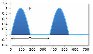
Sine pulse after half-wave rectification - only positive half-wave
Parameters
Basic formulas
Example calculations
Practical calculation examples
Example 1: Standard half-wave rectification
Given: Us = 10V (peak voltage of the sine wave)
Example 2: Rectified mains voltage
Given: Us = 325V (peak of 230V mains voltage)
Example 3: Low voltage application
Given: Us = 5V (small signal voltage)
Ratios for half-wave rectification
RMS ratio:
Mean value ratio:
Theory of Half-Wave Rectification
What is half-wave rectification?
To calculate the RMS voltage and the mean voltage (or average voltage) of a half-wave rectification, proceed step by step. In a half-wave rectification, only the positive part of the sinusoidal AC voltage is used. The negative half-wave is cut off or blocked.
RMS voltage after half-wave rectification
The RMS value is defined as the DC value with the same thermal effect as the considered AC value. For a sinusoidal AC voltage without rectification, the RMS value is Ueff = Us/√2.
After half-wave rectification, only the positive part of the sine wave is used, and the RMS voltage can be calculated with a different formula. It results from the quadratic mean over half a period:
RMS value formula
The RMS value is exactly 50% of the peak voltage.
Mean voltage after half-wave rectification
Since we only use the positive part of the sine wave, the mean value of the voltage after half-wave rectification is:
Mean value formula
The mean value is about 31.8% of the peak voltage.
Mathematical derivation
Calculation of the RMS value
For a half-wave rectified sine over a full period T:
Calculation of the mean value
The mean value is calculated over a full period:
Practical applications
Power supplies
- Simple rectifiers
- Low cost
- High ripple voltage
- Low efficiency
Signal processing
- Envelope detector
- AM demodulation
- Peak value measurement
- Rectification of weak signals
Measurement technology
- Simple RMS measurement
- Average value measurement
- Calibration circuits
- Reference voltages
Comparison with other rectifications
Rectification comparison
Ueff = Us/√2 ≈ 0.707Um = 0V
Ueff = Us/2 = 0.5Um = Us/π ≈ 0.318
Ueff = Us/√2 ≈ 0.707Um = 2Us/π ≈ 0.637
Design notes
Practical considerations
- Low efficiency: Only 50% of the available energy is used
- High ripple voltage: 100% ripple at mains frequency
- Transformer utilization: Poor utilization of the iron core
- Diode load: High peak current in short pulses
- Filtering effort: Large capacitors required for smoothing
- Application: Only for non-critical applications or very low power
|
|