Sine Pulse RMS Value (Full-Wave Rectification)
Calculator and formulas for calculating the RMS and mean value of sine pulses
Sine Pulse Calculator (Full-Wave)
Full-Wave Rectification
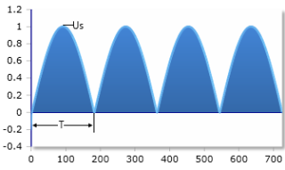
This function calculates the RMS and mean value of a sine pulse from a full-wave rectification. Both half-waves are rectified.
|
|
Full-Wave Rectification

Sine pulse after full-wave rectification - both half-waves rectified
Parameters
Basic formulas
|
|
Example calculations
Practical calculation examples
Example 1: Standard full-wave rectification
Given: Us = 10V (peak voltage of the sine wave)
Example 2: Rectified mains voltage
Given: Us = 325V (peak of 230V mains voltage)
Example 3: Low voltage power supply
Given: Us = 17V (12V transformer with √2 factor)
Ratios for full-wave rectification
RMS ratio:
Mean value ratio:
Theory of Full-Wave Rectification
What is full-wave rectification?
In full-wave rectification, both the positive and negative parts of the sinusoidal AC voltage are used, so the entire wave is converted into positive voltages. This leads to significantly better energy utilization compared to half-wave rectification.
RMS value after full-wave rectification
The RMS value is defined as the DC value with the same thermal effect as the considered AC value. The RMS voltage after full-wave rectification is the square root of the mean square value over the entire period. Since both half-waves are used, the RMS value remains the same as the original sine wave.
RMS value formula
The RMS value is the same as for a normal sine wave (≈ 70.7%).
Mean value after full-wave rectification
The mean voltage (average voltage) after full-wave rectification is calculated from the mean value of the entire positive and negative half-waves. Since both half-waves are rectified, the mean value is twice as high as for half-wave rectification.
Mean value formula
The mean value is about 63.7% of the peak voltage.
Mathematical derivation
Calculation of the RMS value
For a full-wave rectified sine over a full period T:
Calculation of the mean value
The mean value is calculated over a full period:
Practical applications
Power supplies
- Standard rectifiers
- High efficiency
- Low ripple voltage
- Good transformer utilization
Industrial applications
- DC motor drives
- Battery chargers
- Electroplating systems
- Welding equipment
Electronics
- Amplifier power supplies
- LED drivers
- Voltage regulator inputs
- Laboratory power supplies
Comparison of rectification types
Rectification comparison
Ueff = Us/√2 ≈ 0.707Um = 0VAC
Ueff = Us/2 = 0.5Um = Us/π ≈ 0.31850% efficiency
Ueff = Us/√2 ≈ 0.707Um = 2Us/π ≈ 0.637100% efficiency
Advantages of full-wave rectification
Electrical advantages:
- Double efficiency: 100% vs. 50% for half-wave
- Lower ripple: 100Hz vs. 50Hz fundamental frequency
- Better utilization: Transformer and diodes
- Higher voltage: Double mean value
Practical advantages:
- Smaller filters: Less capacitor capacity required
- Better regulation: More even DC voltage
- Less heating: Lower losses
- Standard solution: In most power supplies
Design notes
Practical considerations
- Circuit types: Bridge rectifier or center-tap circuit
- Diode voltage rating: At least 1.4 × Us (bridge) or 2.8 × Us (center-tap)
- Current load: More even distribution on the diodes
- Transformer design: Better utilization of the iron core
- Filter design: Capacitor for 100Hz (i.e. 2 × fmains) dimensioning
- Cost efficiency: Higher initial investment, but better overall efficiency
|
|